
Developing Novel Spectroscopy Techniques Using a Segmented Cross Undulator
I. Matsuda Group
Cross undulators, composed of a single set of insertion devices for linear horizontal and vertical polarization with a phase shifter in between, have become available at worldwide synchrotron and x-ray free electron laser facilities. To achieve higher degree of the light polarization, a segmented type of the cross undulator, was designed and successfully installed at SPring-8 BL07LSU [1]. At the beamline, the continuous variation of the phase shifts has realized smooth polarization controls of soft X-ray beam between linear and circular ones with fast switching (13 Hz) [1]. The oscillatory regulation has allowed us to determine the element-specific complex permittivity in soft X-ray [1]. In the present research, we demonstrated a new control of linear polarization at any angle with a segmented undulator.
The segmented cross undulator at SPring-8 BL07LSU is composed of eight segments of insertion device (ID) and seven phase shifters (PSs), as shown in Fig. 1 (a). The ID segment is a horizontal figure-8 undulator or a vertical figure-8 undulator. The horizontal (H) and vertical (V) ID segments are placed alternatively and sandwich a PS. A PS is used to adjust the relative phase of radiation emitted from each segment by changing the path length of the electron orbit in magnetic field. To realize linearly polarized light with arbitrary angle, θ, we combine two waves of the left- and right-handed circularly polarized light, generated by sets of the ID segments, Set A and Set B, as shown in Fig.1(a). Set A or B is composed of the two H and two V segments. When Set A produces right-handed (left-handed) circular polarized light, we make Set B generate lefthanded (right-handed) circular polarized light. Then, the rotation angle (θ) of linearly polarized light is controlled by changing the phase shift between the left and right circularly polarized light at the center PS. In other words, we can generate soft X-ray beam with linear polarization that continuously rotates its angle over 2π.
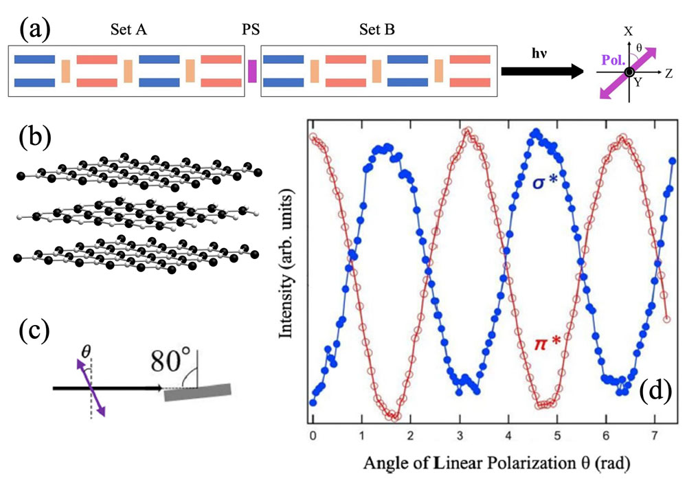
Fig. 1. (a) A schematic drawing of the segmented undulator with H (blue) and V (red) ID segments and PS’s (orange). (b) An illustration of a h-BN film. (c) The measurement configuration. (d) The rotational NEXAFS spectra at the π* peak (hν = 401.5 eV) and the σ* peak (hν = 408.0 eV) [2].
For demonstration, we made measurements of near-edge X-ray absorption fine structure (NEXAFS) on a 2D film of h-BN (Fig. 1(b)) [2]. Focusing on the π* and σ* NEXAFS peaks, we traced their intensity variations with angle of the linear polarization, θ. Since this NEXAFS methodology is different from the conventional one, we hereafter call it the rotational NEXAFS measurement. When the incident angle is 80o, as illustrated in Fig. 1(c), intensity of hν = 401.5 eV (π*) becomes the maximum at θ = 0, π, 2π (horizontal) and the minimum at θ = π/2, 3π/2 (vertical), while that of hν=408.0 eV (σ*) shows the opposite, as shown in Fig. 1(d). The rotational NEXAFS experiment enhances the clear electronic contrast between the π* (out-of-plane) and σ* (in-plane) orbitals of h-BN. The experimental plot is expected to be useful in making assignments of the electronic states and in determining the precise configuration of molecules.
Figure 2 shows another demonstration of the rotational X-ray spectroscopy experiment of the X-ray magnetic linear dichroism (XMLD) [3]. Figure 2 (a) shows an Ni L-edge XAS spectra of a NiO crystal taken with horizontal and vertical linearly polarized light at the incident angle of 80° from the surface normal. XMLD spectra of the NiO crystal is obtained by taking difference between the XAS spectra taken with the horizontal and vertical linear polarizations (Fig. 2 (b)), showing clear linear dichroisms. Focusing on the L2a and L2b peaks, the former has a large horizontal intensity, while the latter has a large vertical intensity. The spectral feature appears opposite in the XMLD signals. Figures 2(c,d) show results of the rotational XMLD, taken at the incident angle of 80°. The intensity changes with a period of π, showing a clear XMLD contrast. The reversed features between the ID section orders confirm the genuine XMLD signals (red and blue lines in the figure). The technique can be combined with a lock-in-amplification and it is expected to detect fine magnetic signals of various materials.
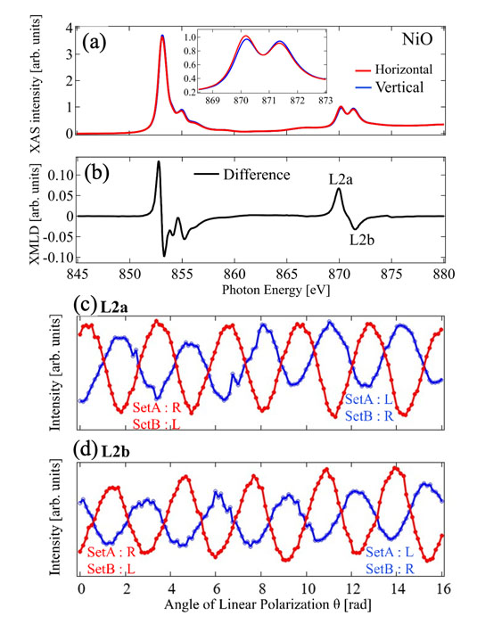
Fig. 2. (a) XAS and (b) XMLD spectra of a NiO crystal at the Ni L-edge and at an incident angle of 80o. In (a), the red (blue) curve indicates a spectrum, taken by the horizontal (verticals) linear polarization. (c)(d) Plots of the Rotational XMLD, shown as intensity at the L2a (hν = 869.95 eV) and L2b (hν = 871.55 eV) peaks at various angles of linear polarization. The red plot shows the results for Set A with right-handed polarization and Set B with left-handed polarization, while the blue plot shows the results with the opposite polarization configuration [3].
References
- [1] J. Miyawaki, S. Yamamoto, Y. Hirata, M. Horio, Y. Harada, and I. Matsuda, AAPPS Bulletin 31, 25 (2021).
- [2] Y. Kudo, Y. Hirata, M. Horio, M. Niibe, and I. Matsuda, Nucl. Instrum. Meth. Phys. Res. A 1018, 165804 (2021).
- [3] Y. Kudo, M. Horio, Y. Hirata, T. Ohkochi, T. Kinoshita, and I. Matsuda, e-J. Surf. Sci, Nanotechnol. 20, 124 (2022).