
Sub-Atomic Lattice Distortion of an Atomic Layer Compound Visualized by Moiré Pattern
Komori Group
Chemical and physical properties are greatly affected by lattice distortion through the change of the electronic structures. At solid surfaces, the local distortion induced by the adsorbates, subsurface impurities and hetero-interface modify reactivity, growth and other atomic processes. By mapping the amplitude and direction of the local distortion, we can elucidate the details of the atom processes including surface reactivity. However, it has been technically difficult to observe the local distortion directly using microscopy methods. While scanning tunneling microscopy (STM) with atomic resolution is one of the ideal tools for studying the local structure, its lateral resolution is still insufficient to measure the distortion of the order of a few % of the lattice constant [1]. One of the ways to improve the lateral resolution is a use of the moiré pattern in the STM images [2]. In the present study, we demonstrate that the local lattice distortion of a hexagonal iron-nitride monatomic film grown over a flat and wide Cu terrace can be visualized by analyzing the moiré pattern [3].
Observed topographic STM images of the surface are shown in Fig. 1(a. b). A uniform iron-nitride film grows over the Cu(111) terrace larger than 100 × 100 nm2, and a hexagonal moiré pattern with the periodicity of ~ 1.3 nm can be seen in the images. The green circles in Fig. 1(a) show the positions of the surface atoms along the [101] direction, and the cyan line is plotted along the moiré pattern. The latter is tilted from the lattice orientation of the hexagonal iron nitride monolayer by 1.1 ± 0.1°. A schematic model of the iron nitride monolayer on Cu(111) is displayed in Fig. 1(c). We assume that Fe atoms are observed as protrusions by STM. This model can reproduce the overall characteristics of the moiré pattern in the image including the 1.1° tilt as in Fig. 1(d). In the STM images, we notice larger and higher protrusions, which randomly distribute on the surface, than the atomic protrusions as indicated by the red circle in Fig. 1(a). We call them point protrusions.
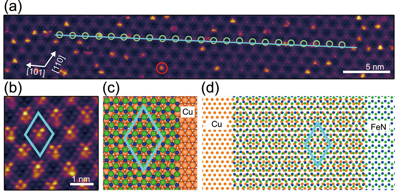
Fig. 1. (a,b) Topographic STM images of the hexagonal iron-nitride monolayer on Cu(111). Cyan line in (a) is drawn along the moiré pattern. The lattice orientation of the iron-nitride monolayer is indicated by green circles in (a). The red circle in (a) indicates the point protrusion. (c) Schematic model of the hexagonal iron-nitride monolayer on Cu(111). Green, blue and orange balls indicate Fe, N and Cu atoms, respectively. The Cu(111) lattice is rotated by 0.28° from the iron-nitride lattice. (d) Moiré pattern between the hexagonal iron-nitride monolayer and Cu(111) obtained by the schematic model in (c). Cyan rhombuses in (b), (c) and (d) show the unit cell of the moiré pattern [3].
A detailed analysis of the moiré pattern reveals that the center of the moiré pattern does not form a regular periodic lattice. The center positions randomly fluctuate from a hypothetical regular lattice points. Figure 2(a) shows a two dimensional histogram of the displacement of the moiré pattern center from the lattice point and the distance from the center of the moiré pattern to the nearest point protrusion. Our structural model of the point protrusion is given in Fig. 2(b). The histograms of the distance from the centers to the nearest point protrusions are made depending on the displacement to see the correlation more clearly as in Fig. 4(c−e). For the centers with a large displacement, the distance to the nearest point protrusion is relatively short compared to those with a small displacement. The point protrusions are preferentially formed in the regions with large lattice distortion of the iron nitride monolayer.
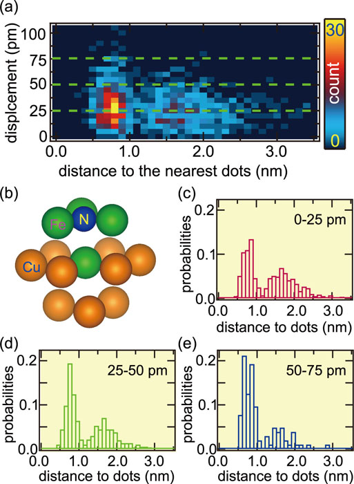
Fig. 2 (a) Two-dimensional histogram of the displacement of the moiré pattern center and the distance from the center to the nearest point protrusion. (b) Proposed schematic model of the point protrusion. (c−e) Histograms of the distance from the centers to the nearest point protrusions for three regions of the displacement 0- 25 pm in (c), 25−50 pm in (d), and 50−75 pm in (e). The counts are normalized by the total counts in each region [3].
References
- [1] S. Ohno et al., Surf. Sci. 554, 183 (2004).
- [2] M. Ritter et al., Phys. Rev. B 57, 7240 (1998).
- [3] T. Hattori et al., Nano Lett. 21, 2406 (2021).