
Electric Control of Flying Qubit on Quantum Hall Edge Channels
Katsumoto Group
For composing a quantum circuit with electron spins, “flying qubits” (FQs) are used for transferring quantum information between qubit clusters. A simple realization of FQ is an electron wave packet, which brings 1 qubit information as its spin. In a flight process, quantum decoherence, i.e. loss of information should be avoided, and also a unitary operation on the FQ is desirable. In the quantum Hall effect one-dimensional channels are formed at the sample edges (quantum Hall edge channel, QHEC) and the quantum coherence of electronic states on them are robust against disturbances from the environment. Also when the magnetic field is strong enough, the electronic states of QHECs are spin-polarized due to the Zeeman energy and the exchange effect (quantum Hall ferromagnet). Hence in a spin up and down pair of QHEC, the spin and orbital degrees of freedom are quantum mechanically entangled. If one can separate an electron wave packet into two QHECs in such a pair, operations on the orbitals readily change the spin states. For example, spin precession can be realized through the Aharonov-Bohm (AB) interference. Here we report unitary operation of FQs on QHECs by using non-adiabatic inter edge channel tunneling.
Figure 1(a) shows the scheme of the unitary operation. From the right end, an electron wave packet with up spin is injected into QHEC-1 and experiences partial inter-edge tunneling to QHEC-2, which corresponds to a gain of zenith angle in electron. During the travel to the left crossing, a phase difference is given, which corresponds to an azimuth angle rotation. The partition rate to QHEC-1 reflects both zenith and azimuth angles. We realized such quantum interference circuits on semiconductor (AlGaAs/GaAs) two-dimensional system (2DES) and micro-fabricated Schottky gates on it. In Fig.1(b), we illustrate the channels for FQs, the terminals and measurement circuits superposed on an optical micrograph of the sample gate configuration on a 2DES. The first crossing point is realized by Gate SR as a sharp corner, where inter edge tunneling is caused by spin-orbit interaction. The phase difference between QHEC-1 and 2 is developed during the travel along the down edges of Gate SR, C and SL. This process corresponds to the precession of the spin around the zenith axis (z-axis). At the left end of the device, the two QHEC are intermixed again and the total transmission rate to the electrode L reflects both zenith and azimuth angles.
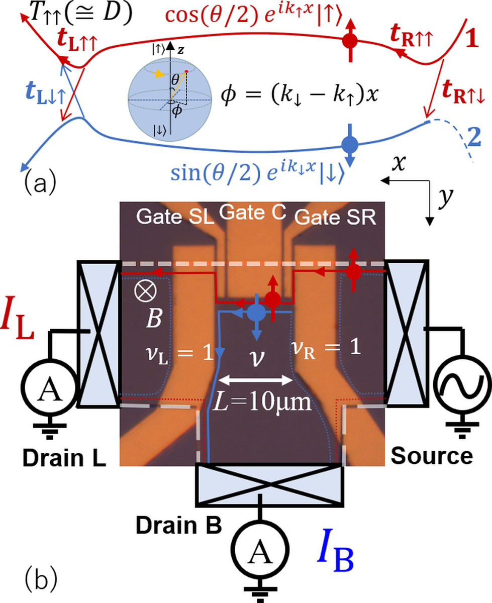
Fig. 1. (a) Schematic diagram of unitary operation on an electron spin flying qubit. An FQ is injected to channel-1 and some portion of the wave packet tunnels into channel-2 with down spin (gaining of zenith angle.) During the travel, the FQ gains azimuth angle via the difference in the kinetic phase. The spin state is detected as the overall transmission amplitude. (b) Optical micrograph of metallic gates (regions with orange color) configuration fabricated on a 2DES. Edge conduction channels and measurement circuits are illustrated and superposed.
In Fig. 2, we plot the current partition ratio (distribution ratio, D) to drain L as a function of the gate voltage applied to gate C (VC). The parameter is the gate voltage applied to gate SR (VSR). A large oscillation versus VC is visible and the amplitude strongly depends on VSR. The oscillation is a consequence of interference in kinetic phases of QHEC-1 and 2, or equivalently precession of electron spin (azimuth angle rotation) [1]. Here VC is changing the distance between the two channels. The amplitude depends on the zenith angle of the spin, and should be largest making the visibility 100%, when the spin is in xy-plane. Hence from the amplitude we can deduce the zenith angle, e.g. 14 degree for VSR = -0.549 V.
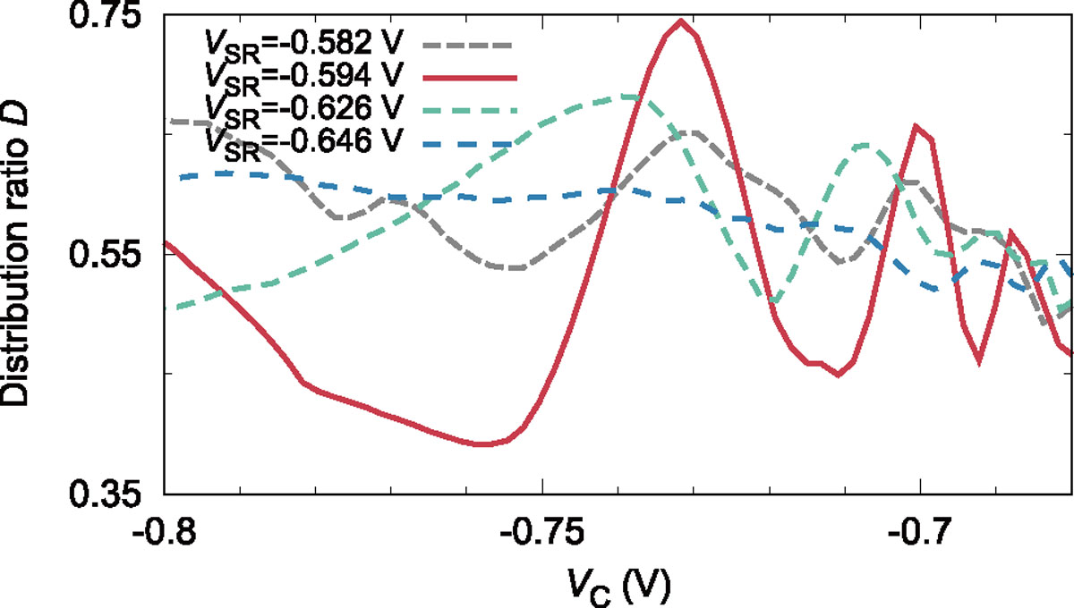
Fig. 2. Current distribution ratio to drain L, which is equal to the overall transmission coefficient of channel-1 in Fig.1(b) as a function of center gate voltage.
From the above, we conclude that unitary operation on electron spin FQ can be done electrically by using spin-polarized QHEC.
References
- [1] T. Nakajima, K. T. Lin, and S. Komiyama, AIP Conf. Proc. 1566, 301 (2013).