
Indoor World Record of 1200 T Achieved by the Newly Installed Electromagnetic Flux Compression Megagauss Generator
Takeyama and Y. H. Matsuda Groups
The megagauss laboratory, ISSP, UTokyo, has a long history of generations of megagauss fields, using electromagnetic flux compression (EMFC) since the original work in the late 1970s led by the Chikazumi and Miura group. The 1000 T project was revisited in 2010 and 2011, supported by the funding of the MEXT for the promotion of the basic science, and since then, we have devoted ourselves to the installation of the megagauss generation system and the technical improvements. Condenser bank units with 20 kV, 2 MJ for the seed feed coils, and two sets of the main condenser bank units, 5 MJ and 2 MJ each with 50 kV charging capability have been incorporated. The system consisting of these condenser modules has been installed, and tuning for operation was recently completed in 2019. The giant collector plates and the load coil clamping units have been placed in antiexplosion chambers. Designs of the instruments were optimized for substantial improvement in the electromagnetic field energy conversion efficiency. Using the newly installed system, we have successfully generated ultra-high magnetic fields reaching 1200 T.
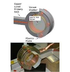
Fig. 1. Overall view of the CL coil and the measurement probe setting. The liner vacuum chamber (made of the Bakelite cylinder and the acrylic resin plastic plates) with the measurement probe is firmly furnished to the CL primary coil with high precision.
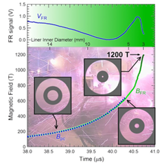
Fig. 2. Magnetic field intensity recorded up to 1200 T with an evolution of time. Upper panel: Faraday rotation signal (VFR) synchronized with the magnetic field intensity. The dotted line taken from the pickup coil (BPC), measured up to 600 T, and the green solid line measures the fields up to 1200 T by FR (BFR). The liner imploding images are shown by black circles. The estimated liner inner diameter at each magnetic field intensity is given in axis of abscissa.
The magnet coil used in the EMFC method is comprised of a single-turn steel outer (primary) coil lined with a copper plate inside (the copper-lined (CL) coil; see Fig. 1) and the so-called liner (a thin metal cylinder, made of copper) which is coaxially set inside the primary coil. A pair of seed field coils set on either side of the primary coil [1]–[3] provides the initial magnetic flux. The liner compresses the magnetic flux and generates megagauss magnetic fields. The EMFC utilizes the electric energy source stored in the condenser bank modules. A record-breaking indoor generation of magnetic field was achieved by discharging 45 kV, 3.2 MJ energy out of 5 MJ condenser units. The liner (typical size is 119 mm diameter, 1.5 mm thickness, approximately 50-mm length) undergoes high-speed implosion (above 5 km/s) accelerated by the magnetic force induced by a huge electric current injected to the primary coil (3–4 mega-Ampere) about its circumference, and the magnetic flux (3.2 T) initially generated in a large volume (diameter 120 mm, length 50 mm) is compressed finally into a small space (3 mm diameter, 20–30 mm length), and reaches a megagauss magnetic field of up to 1200 T. The CL coil was designed to improve the energy transfer efficiency of the imploding liner. The copper lining part bears the current, whereas the massive outer steel coil holds the inertia for the liner acceleration. A liner vacuum chamber with measurement probes are attached to the steel outer coil as shown in Fig. 1. Thus, measurement probes are set precisely at the liner implosion center with respect to the CL coil.
The signals obtained in this work are plotted in Fig. 2. Details are provided in our recent paper [4]. The dotted line is a signal taken from the pickup coil and traced up to 600 T, which is the limit of recording because of the high-voltage induced by the rapid increase of the field. The Faraday rotation signal was intact until the very end of the liner implosion. The green solid line represents the field record after the Faraday rotation signal is converted into the magnetic field intensity. A slow-down effect was observed followed by the peak field prior to the liner “turn-around” phenomenon. Circles depicted in the graph shows images of the liner cross-section during implosion. The liner inner diameter, which corresponds to the bore of the coil, is shown as a guide in the axis of abscissa in the middle of the figure. Final diameter of the liner at 1200 T is estimated to be 3 mm. The maximum speed of the liner during the implosion is estimated to be higher than 5 km/sec, which is consistent with the “Hugoniot curve” [5], in which a field of 1200 T hits at 5.3 km/sec.
References
- [1] N. Miura and F. Herlach, Springer Topics in Applied Physics 57, 247 (Springer, Berlin, 1985).
- [2] F. Herlach, Rep. Prog. Phys. 62, 859 (1999).
- [3] N. Miura and F. Herlach, High Magnetic Fields-Science and Technology 1, 235 (World Scientific, 2002).
- [4] D. Nakamura, A. Ikeda, H. Sawabe, Y. H. Matsuda and S. Takeyama, Rev. Sci. Instrum. 89, 095106 (2018).
- [5] F. Herlach, Rep. Prog. Phys.62, 859 (1999).