
Electro-Magnetic Flux Compression Went Over 700 T
Takeyama Group
The electro-magnetic flux compression (EMFC) technique is the only one way to obtain magnetic fields over 300 T without using chemical explosives. We have a long history of developing the so called the “Cnare method” since early 1970s.[1] In early 2000s, the maximum magnetic field (Bmax) has reached around 600 T by introducing the “feed-gap compensator” which contributed substantially to improved spatial symmetry of the liner implosion for magnetic flux compression. [2] We have succeeded the technical exploitation of the EMFC since 2004, and started to employ a new primary coil system, a copper lined (CL) coil, which comprises of a steel outer coil with a bent copper sheet inside[3-6]. The new technique is found to be promising for the EMFC performance. The highest magnetic field which we have recently achieved is over 700 T. The world record is renewed as an indoor experiment. In this article we present recent results obtained from the technical developments based on the CL coils.
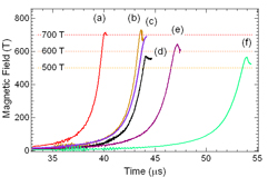
Fig.1. Time evolution of pickup coil signals recording a magnetic field conducted by various conditions. The parameters of the coils are listed in Table 1. The upper photo shows the copper lined primary coil recently developed.
In the CL coil, the inner copper plate coil bears the main primary current flow (around 4 MA). The outer steel coil has a role of gaining a mass to delay the coil deformation during the liner acceleration. In the experiments, the standard coil is comprised of a copper lining coil with an inner diameter 130 mm, the thick 2 mm and the length 45 mm and of the steel outer coil with 135 mm/25 mm/45 mm. The initial size of a copper explosive liner is 119 mm-outer diameter/2 mm-thick/50 mm-length (a, b in Fig.1). The thick of the steel outer coil was reduced to 15 mm in c of Fig.1. The liner thick was decreased to 1.5 mm in a of Fig.1. Large size coils were also employed in e and f of Fig.1. The sizes are listed in Table 1. The liner was placed in an insulated chamber with a vacuum kept at less than 10 Pa. The magnetic field was measured using calibrated pick-up coils, and also evaluated by a Faraday rotation angle of a fused quartz thin plate. A high speed photograph was taken by an IMACON 468 high-speed framing camera. We have an installation of 5 MJ condenser banks (6.25 mF, 40 kV) for storage of an energy injecting into a destructive coil system. A pair of the seed field coil magnets placed adjacent to the primary coil is energized by a capacitor bank of 1.5 MJ (30 mF, 10 kV). A set of new seed coils were wound by a 3.0x6.0 mm normal copper wire, and each coil is composed by 8 turns and 16 layers of the wire. Total inductance of the two coils separated each by 240 mm distance connected in series is 8.3 mH at 20 Hz. At the center position of the primary coil 4.4 T (8.8 T at the center of each coil) is repeatedly generated by a condenser charging voltage of 9.5 kV (1.35 MJ).
Figure 1 summarizes some of our recent records of signals of a magnetic field. The corresponding experimental parameters are listed in Table 1. Three pickup coils separated by 2 mm each other are wounded around a 1 mm diameter stick placed at the center of the liner. Bmax represents the maximum magnetic field among the three pickup coils, and <Bmax>av is the averaged values of the three. The curve (d) recording Bmax=570 T was obtained by a seed field Bs=3.2 T, while a simple increase of Bs up to 3.8 T resulted in a world record showing Bmax=730 T and <Bmax>av= 695 T (curve b). The curves (a-c) are the results of experiments with the same Bs(=3.8 T). Reduction of the mass of the liner increases the speed of the liner implosive motion, and the increase of Bmax is expected according to the so called “Hugoniot “plot[7]. Thickness of the copper liner was reduced to 1.5 mm from 2 mm in curve (a), and the result was Bmax=710 T and <Bmax>av=700 T, almost the same as for a 2.0 mm thick liner regardless of an increased liner implosive speed.
| Bs [T] | Copper Primary Coil [mm] | liner [mm] | speed[km/s] | Bmax [T] | <Bmax>av [T] | |||||
| Steel thick | Inner D | length | Inner D | thick | length | |||||
| a | 3.8 | 25 | 130 | 45 | 116 | 1.5 | 50 | 2.9 | 710 | 700 |
| b | 3.8 | 25 | 130 | 45 | 115 | 2.0 | 50 | 2.4 | 730 | 695 |
| c | 3.8 | 15 | 130 | 45 | 115 | 2.0 | 50 | 2.6 | 690 | 660 |
| d | 3.2 | 25 | 130 | 45 | 115 | 2.0 | 50 | 2.6 | 570 | 540 |
| e | 4.4 | 25 | 140 | 48 | 124 | 2.0 | 53 | 2.2 | 640 | 615 |
| f | 4.0 | 20 | 160 | 56 | 146 | 2.0 | 61 | 2.2 | 565 | 515 |
References
- N. Miura, G. Kido, M. Akihiro, I. Oguro, and S. Chikazumi, Proc. of the Int. Conf. on Phys. in High Magnetic Fields, Grenoble, 345 (1974); N. Miura, G. Kido, M. Akihiro, amd S. Chikazumi, J. of Magn. Magn. Mater. 11, 275 (1979).
- Y. H. Matsuda , F. Herlach, S. Ikeda, and N. Miura, Rev. of Scientific Instruments 73, 4288 (2002).
- S. Takeyama and K. Kindo, J. of Phys. Conference Series 51, 663 (2006).
- E. Kojima and S. Takeyama, J. of Phys. Conference Series 51, 537 (2006).
- S. Takeyama, E. Kojima, K. Kindo, and H. Yokoi, Int. J. of Modern Phys. B21, 1238 (2007).
- E. Kojima and S. Takeyama, in “Megagauss Magnetic Fields and High Energy Liner Technology”, ed. by G. F. Kiuttu, P. J. Turchi, R. E. Reinovsky, IEEE, 217 (2007).
- F. Herlach, in “Megagauss Technology and Pulsed Power Application”, ed. by C. M. Fowler, R. S. Caird, and D. J. Erickson, p.39 (Plenum Press New York 1987).