
Development of Cantilever Magnetometry Technique for Organic Samples and Its Application to TPP[Mn(Pc)(CN)2]2
K. Torizuka, H. Tajima, and Y. Uwatoko
We have developed the cantilever magnetometry technique to investigate magnetic properties of organic samples. A commercially available microcantilever for the atomic force microscopy (AFM) was employed. As shown in Fig. 1, our sample was situated at the tip of the cantilever beam, depending on the plane in which the magnetic field is rotated. The experimental cell in which the sample was mounted was cooled by a 3He refrigerator in a superconducting split-type magnet. The field direction is horizontal and the maximum field strength is 7 T. The magnet can be rotated so that the magnetic field direction can be changed by 360 degrees in a plane perpendicular to a vertical axis.
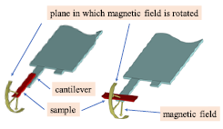
Fig. 1. Sample setup.
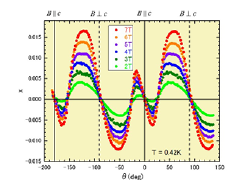
Fig. 2. Torque signal with the field rotated in the plane including c-axis.
For the electrical circuit, two piezoresistors and two metal film resistors (47 kΩ) constituted a Wheatstone bridge. The signal which comes out from the electrical circuit is expressed by the quantity, x ≈ ΔR/Rref (ΔR≡Rref - Rcant, where Rref and Rcanti are piezoresistivities of the reference and the cantilever). This quantity x is proportional to the torque when x is small, but changes nonlinearly as x becomes larger [1].
The advantage of this technique is that even if the sample is very tiny, we can obtain the torque signal. In fact, the mass of our sample is approximately 1 μg. This technique is a very sensitive one.
We carried out magnetic torque measurements for TPP[Mn(Pc)(CN)2]2, that is isostructural to TPP[Fe(Pc)(CN)2]2. The latter is a well-known molecular conductor showing the negative giant magnetoresistance. Our motivation is to clarify the magnetic structure for the former sample. The sample has d4 electrons which behave as a localized magnetic moment with spin S = 1.
The angular dependence of the torque when the magnetic field is rotated in a plane including c-axis is depicted in Fig. 2. The data shows a two-fold symmetry reflecting the crystal structure. The d electron emerges in the curve, which is characteristic for the ferromagnetism. However, since the susceptibility data exhibits the antiferromagnetic behavior, d electron should be interpreted as the canting antiferromagnetism [2].
On the other hand, when the magnetic field is rotated in the ab plane, the torque signal shows a saw-tooth wave form with a four-fold symmetry. It is characteristic for the antiferromagnetic. Considerations on magnetic properties of d electrons as well as π electrons are now in progress.
References
- [1] K. Torizuka et al., Jpn. J. Appl. Phys. 52, 066601 (2013).
- [2] K. Torizuka et al., to be published in J. Phys. Soc. Jpn.