
Coupling of Two Quantum Hall States at Graphene Monolayer/Bilayer Boundary: Bulk-Edge Correspondence between Different Materials
Osada Group
The edge channel transport in the quantum Hall (QH) states has been extensively investigated in graphene systems. The subjects of most studies have been the p-n homo-junction of monolayer graphene (MLG) or bilayer graphene (BLG), since they were the first bipolar QH junctions between electron and hole QH states. The graphene p-n junctions are realized using the dual gate FET devices, in which an additional top-gate electrode partially covers MLG or BLG so as to control the carrier number and polarity of the covered part independently. In this case, both sides of the junction are the same material with the same band structure under different potential energy. The main issue was the mixing between the electron and hole QH edge channels propagating parallel along the junction in both sides.
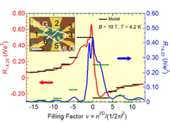
Fig. 1. Hall resistance R14,25 and transverse resistance R14,23 across the MLG/BLG junction. The horizontal bars indicate the quantized values assuming strong coupling limit. Inset: microscope image of the FET device.
Here, we consider another type of QH junctions in the graphene system, namely, the hetero-junction of MLG and BLG. In this case, the both sides of the junction have the same polarity (n-n or p-p junction), but they are different materials (MLG and BLG) with the different band structures: the low-energy band dispersion is the Dirac cone in MLG, but it shows the quadratic band touching in BLG. Under the perpendicular magnetic field B, these energy bands are quantized into the Landau levels (LLs), which have four-fold spin and valley degeneracies. The most characteristic feature is the appearance of the zero-energy LL resulting from the Berry phase of ± π and ± 2π around the band contact points in MLG and BLG, respectively. Note that the zero-energy LLs in MLG and BLG have different degeneracies; four-fold in MLG but eight-fold in BLG in which both the n=0 and n=1 LLs degenerate to zero energy. This fact results in the different quantized values of the Hall conductivity; σxy = N1e2/h = ±(4N + 2)e2/h in MLG and σxy = N2e2/h = ±(4N + 4)e2/h in BLG (N = 0, 1, 2,···). Here, N1 and N2 are the Chern numbers of the QH states in MLG and BLG, respectively. The spin or valley splitting is ignored.
In the present work, we have experimentally studied the QH edge transport across the MLG/BLG junction employing hexagonal boron nitride (h-BN) substrate, which remarkably improves sample quality, and we have clarified the edge channel configuration along the MLG/BLG junction. If the both sides of the junction is perfectly decoupled, there are |N1| and |N2| edge channels in MLG and BLG sides, respectively, so that they propagate in opposite direction along the junction. If finite coupling exists between both sides, they must show pair annihilation resulting in |N1| – n and |N2| – n channels at the boundary. At the strong coupling limit, n = min(|N1|, |N2|), |N2 – N1| channels with the same direction remains at the boundary. These features are required from the bulk-edge correspondence at the boundary of two QH states, which basically originates from the charge conservation law. The coupling feature is not trivial since MLG and BLG have different crystal and band structures. Whereas electronic states in MLG consist of A and/or B site Wannier states, those in BLG mainly consist of A and/or B' site Wannier states. So, the envelope function is not continuous at the MLG/BLG boundary. The coupling depends on the connection of the true wave functions at the boundary.
Figure 1 shows the observed Hall resistance and transverse resistance across the MLG/BLG boundary of the FET device fabricated on h-BN substrate as functions of the filling factor, which is controlled by the back gate voltage. The carrier densities of the MLG and BLG parts are almost same, since the gate voltages of charge neutrality points coincide in both parts. The horizontal bars indicate the quantized values calculated from the Landauer-Büttiker formula assuming the strong coupling limit. The calculation well reproduces the observed result in the positive filling (n-type) region. Considering the BLG side shows imperfect QH effect in the negative filling (p-type) region in the present device, this agreement indicates that the coupling between two QH states at the boundary is so strong that the minimum number (|N2 – N1|) of edge channels survives at the boundary of MLG and BLG.
In the figure, we can see another remarkable feature around the zero filling. The transverse resistance shows fine dip structures. They are considered to reflect the degeneracy breaking of the zero-energy LL in MLG and BLG. Although no perfect splitting was observed in MLG or BLG in the present device, this result suggests the splitting of the edge channels along the boundary.