
Development of a Phase Shifter with Laminated Permalloy Yokes for Multi-Segment Undulators
Nakamura Group
A phase shifter is used to control the radiation phase between two undulator segments by giving a bump orbit to an electron beam with its magnetic field and can be applied to novel undulators such as a polarization-controlled undulator[1, 2] and very long undulators in synchrotron radiation(SR) sources and FELs that have to consist of undulator segments separated by finite distances. The phase shifter generally has to make a phase shift of 0 to 2π or more for all the wavelengths. High stability and reproducibility of the phase control is required to avoid orbit movements of the electron beam and quality degradation of the SR beam. Furthermore fast control of SR wavelength and polarization including helicity switching is often needed for the phase shifter.
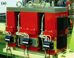
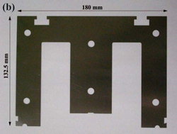
Fig.1. (a) Phase shifter prototype and (b) 0.1-mm-thick permalloy lamination used for the yokes.
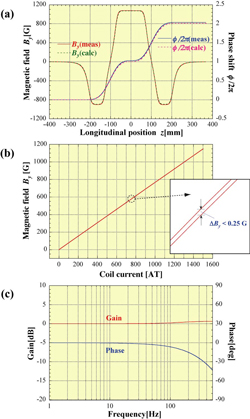
Fig. 2 . Field measurement results: (a) measured longitudinal field distribution and phase shift expected from the distribution with the 3-D field calculation result, (b) excitation curve of Magnet B and its ultra-low hysteresis and (c) frequency response of Magnet A up to 500 Hz.
We designed and fabricated a phase shifter prototype with 0.1-mm-thick permalloy laminations to satisfy the requirements for the phase shifter. The phase shifter prototype consists of three H-type dipole magnets (Magnet A, B and C) with the yoke-length ratio of 1:2:1. Each magnet has a yoke divided into two parts at the horizontal symmetric plane and two coils for the upper and lower magnetic poles. Figure 1(a) shows the fabricated phase shifter prototype. Each half yoke is made of 0.1-mm-thick permalloy laminations united and insulated by varnish. Figure 1(b) shows a permalloy lamination used for the yokes. All the permalloy laminations are formed by stamping and annealed at about 1100 °C to maximize their magnetic permeability. We succeeded in reducing the size error of the laminations down to ±0.1 mm even after annealing. They have a very high magnetic permeability (about 400000) and very low hysteresis. The three magnets are independently excited by three identical power supplies, which are linear amplifier type and developed so that it should have good frequency response and low ripple and drift less than 100 ppm (10-4) of the maximum current.
Field measurements were performed using a 3-D field measurement system with a Hall probe and a 3-D movable stage. Figure 2(a) shows the measured longitudinal field distribution and the phase shift due to the field distributions at coil currents of IA=IC=-1170 AT and IB=1400 AT. The measurement result is in good agreement with the result of 3-D magnetic field calculation. The maximum phase shift given by this prototype is about 4π for an assumed maximum radiation wavelength of λ=4.959 nm (250 eV). Figure 2(b) shows the excitation curve of Magnet B and its hysteresis effect. The excitation curve is almost linear and the magnetic field is not saturated up to the maximum coil current of 1500 AT. Due to the ultra-low hysteresis of the yoke, the hysteresis effect was only 0.25 G at maximum. Figure 2(c) shows measured frequency response of Magnet A. The gain was kept constant within 1 dB up to 500 Hz and the phase delay was less than 1 degree at 10 Hz and 10 degrees at 100 Hz. The phase shifter prototype with laminated permalloy yokes showed good performance in reproducibility and frequency response of the magnetic field.
References
- M. Oshima and A. Kakizaki, Journal of JSSRR 20, No. 6, 383 (2007).
- T. Tanaka and H. Kitamura, AIP Conference Proceedings 705, 231 (2004).